4 of 52: FC3S RX7 IGN1A Ignition Coil Mount
QUICK SPECS
Estimated Time Of Completion: 20 Hours
Material Used: eSun PA-CF
Products Used: Fusion 360, Creality K1 Max, Einstar Shining 3D Scanner
Number of Revisions: 6
Difficulty: Medium
Ease to Mass Produce: 9/10 (Run these in batches of 7-8 at a time easily)
Sometimes designs are personal problems that turn into products. I’ve been building my 1988 FC3S RX-7 and found myself in need of a bracket to mount my ignition coils. I was made acutely aware of limited to no market options available for a very common part. So I go to work making my own. This one went through several iterations and involved a pretty length R&D phase.
Design considerations:
Durability against High Frequency Vibrations
Durability against high engine bay temps and temperature from direct contact with coils
Retain OEM Ignition Coil Bracket Mounts
Keep price affordable for an underserved/lower end budget market

FC3S Engine Bay Scan from Einstar Scanner
I started with a 3D Scan of the engine bay in the section I was going to place the mount. Using my scanner, I was able to get a very acceptable result. Some of the angles required are pretty organic, so it was imperative to make sure that I got the measurements bang on.
From there, I got to modeling. Used some IGN1A coil .STEP files I found from the manufactuer and placed them where I wanted them relative to the engine bay. From there, I worked backwards to design the bracket.

The initial rough, coarse design. Planned on making it a 2 part design, but eventually decided a 1 part design would be the cleanest and best solution. I found rigidity of the single piece far exceeded my initial expectations.

The V1 of the mount before iterations
The first iteration nailed the fitment perfectly, but I still wasn’t 100% satisified with the aesthetics. Namely, the ability to read the labels of which hole is designated to which coil on the engine didn’t resolve very well on the 3d print. Some of the edges were too sharp for my liking. Being a part that has smooth a lot of smooth radius bends, I wanted to take a moment to make sure the aesthetics matched. The solution should be minimalistic and sleek while provided function.

The mount with coils from the 3d scan

Version 1 fitment test
After I printed my first one and 100% confirmed fitment, I went back and touched up the aesthetics of the design. I rounded off some more of the corners, bolstered the thickness on some of the faces to make it stronger. I also felt the clearances for the recesses to allow for wrenches to tighten the fasteners were a little too wide so I took the time to clean them up and make them smaller. I had done this to account for potential issues with fitment if the scan had been off a couple mm.

An iteration where I tried to emboss the labels, but still found them too small. Also added the logo and shrunk the holes for the bolts and nuts.
As I had repeatedly iterated, I would find small tweaks here and there that made the design a slight bit better, but they were ultimately still diminishing returns. I landed somewhere I was happy with, the only last piece I needed to fix was the size of the labels on the mount itself. so I ended up making them significantly larger, umissably so.

The final version of the bracket
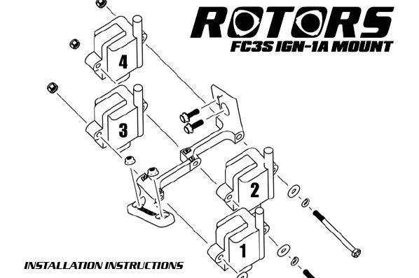
That wasn’t all. Because I knew I was planning on offering this as a full package product, I wanted to make sure the installation was as easy as possible. So I took the time to learn how to diagram and label parts for an instruction manual. I employed my InDesign and Photoshop skills and came up with a 1 page manual I found extremely aesthetically pleasing.
